



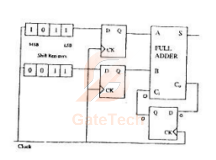
For the circuit shown in figure below, two -bit parallel-in serial-out shift registers loaded with the data shown are used to feed the data to a full adder. Initially, all the flip-flops are in clear state. After applying two clock pulses, the outputs of the fulladder should be
View answer
Answer: D
Worked explanation not available yet.
Free practice · Your answers on this page are not saved.