



In the circuit shown in the figure is a parallel-in, parallel-out bit register, which loads at the rising edge of the clock . The input lines are connected to a bit bus, Its output acts as the input to a ROM whose output is floating when the enable input is A partial table of the contents of the ROM is as follows
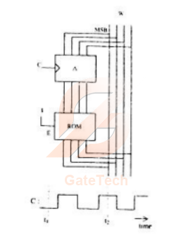
The clock to the register is shown, and the data on the bus at time is The data on the bus at time is
View answer
Answer: C
Worked explanation not available yet.
Free practice · Your answers on this page are not saved.