



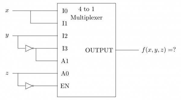
Consider the following multiplexer where are four data input lines selected by two address line combinations respectively and is the output of the multiplexor. EN is the Enable input.
The function implemented by the above circuit is
View worked solution
Answer: A
To find the function implemented by the multiplexer, we analyze the inputs, selection lines, and the enable input from the circuit diagram:
- Select Lines:
- Data Inputs:
- Enable Input (): The enable input has an active-low bubble and is connected to the variable . Therefore, the multiplexer is active only when , which corresponds to .
The general output expression for a 4-to-1 multiplexer with an active-low enable input is:
Substituting the given values into the expression:
Thus, the function implemented by the circuit is , which corresponds to Option A.
Free practice · Your answers on this page are not saved.