

Skip to content
Official PYQ · 1987

GATE CS 1987 Q1-IV — Combinational Circuits

Explain with AI

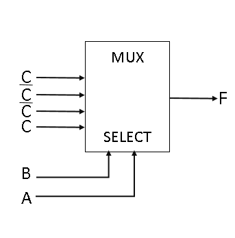
The output FF of the below multiplexer circuit can be represented by
Choose one option
View worked solution

Answer: B

The given circuit is a standard 44-to-11 multiplexer (MUX) with select lines S1=AS_1 = A and S0=BS_0 = B.

The inputs connected to the multiplexer data lines are:

  • I0=CI_0 = C
  • I1=CˉI_1 = \bar{C}
  • I2=CˉI_2 = \bar{C}
  • I3=CI_3 = C

The output equation of a 44-to-11 multiplexer is given by:

F=AˉBˉI0+AˉBI1+ABˉI2+ABI3F = \bar{A}\bar{B}I_0 + \bar{A}BI_1 + A\bar{B}I_2 + ABI_3

Substituting the input values into the equation:

F=AˉBˉC+AˉBCˉ+ABˉCˉ+ABCF = \bar{A}\bar{B}C + \bar{A}B\bar{C} + A\bar{B}\bar{C} + ABC

This is the sum-of-minterms expansion for the 33-variable XOR (odd-parity) function:

F=A⊕B⊕CF = A \oplus B \oplus C

Free practice · Your answers on this page are not saved.

Published
Report a correction
Keep exploringMore Combinational Circuits questions