



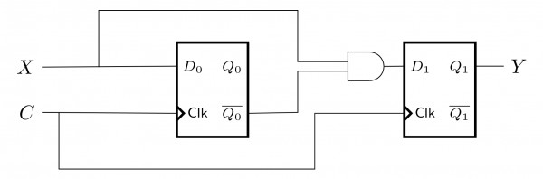
Consider the following circuit with initial state . The D Flip-flops are positive edged triggered and have set up times 20 nanosecond and hold times
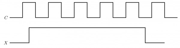
Consider the following timing diagrams of X and C. The clock period of nanosecond. Which one is the correct plot of Y?
View worked solution
Answer: A
To determine the correct waveform for , we trace the state transitions of the two D flip-flops, and , at each positive edge of the clock .
From the circuit diagram, the inputs to the flip-flops are:
The output is given by the AND gate: .
Given that the setup time is and the clock period is , the inputs satisfy the setup and hold time requirements. Let's analyze the state transitions at each positive clock edge:
- Initial State: , . Thus, .
- First Positive Edge:
- has been high () for more than before this edge, so becomes .
- takes the previous value of , which was .
- Thus, .
- Second Positive Edge:
- has been low () for more than before this edge, so becomes .
- takes the previous value of , which was .
- Thus, .
- Third Positive Edge:
- remains , so becomes .
- takes the previous value of , which was .
- Thus, .
Therefore, is high () only during the interval between the first and second positive clock edges, which corresponds to the waveform shown in Option A.
Free practice · Your answers on this page are not saved.