



Consider the following data path diagram.
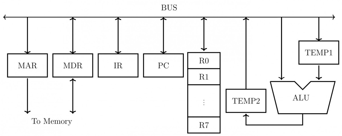
Consider an instruction: . The following steps are used to execute it over the given data path. Assume that PC is incremented appropriately. The subscripts and indicate read and write operations, respectively.
Which one of the following is the correct order of execution of the above steps?
View worked solution
Answer: C
To execute the instruction , the processor must perform the instruction cycle phases in the following sequence:
-
Instruction Fetch (IF):
- First, the address in the Program Counter () is transferred to the Memory Address Register (), and a memory read operation is initiated:
Step 3: - Once the instruction is fetched from memory into the Memory Data Register (), it is loaded into the Instruction Register ():
Step 5:
- First, the address in the Program Counter () is transferred to the Memory Address Register (), and a memory read operation is initiated:
-
Instruction Decode & Execution:
- In a standard single-bus data path, the ALU cannot receive two operands directly from the bus simultaneously. Thus, one operand () is first read and stored in a temporary register ():
Step 2: - Next, the second operand () is placed on the bus, the value in is read, both are added by the ALU, and the result is stored in :
Step 1: - Finally, the result stored in is written back to the destination register :
Step 4:
- In a standard single-bus data path, the ALU cannot receive two operands directly from the bus simultaneously. Thus, one operand () is first read and stored in a temporary register ():
Combining these steps in order gives: .
Therefore, the correct option is C.
Free practice · Your answers on this page are not saved.