



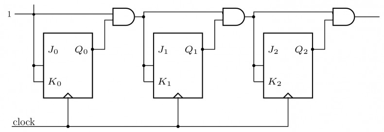
Find the maximum clock frequency at which the counter in the figure below can be operated. Assume that the propagation delay through each flip flop and each AND gate is . Also, assume that the setup time for the inputs of the flip flops is negligible.
View worked solution
Answer: 33.33
In a standard synchronous binary counter with cascaded carry logic, the inputs to the successive flip-flops are generated using a chain of AND gates. For a 4-bit synchronous counter, the inputs to the most significant flip-flop () are given by , which is implemented using two cascaded AND gates:
The critical path (longest delay path) starts from the clock edge triggering the first flip-flop () and propagates through the two cascaded AND gates to reach the inputs of the last flip-flop ().
The minimum clock period required for stable operation is:
Given:
- Propagation delay of each flip-flop,
- Propagation delay of each AND gate,
- Setup time,
Substituting these values:
Thus, the maximum clock frequency is:
Free practice · Your answers on this page are not saved.