



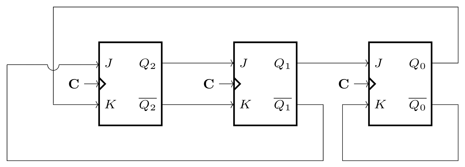
The above synchronous sequential circuit built using JK flip-flops is initialized with . The state sequence for this circuit for the next clock cycles is
View worked solution
Answer: C
By analyzing the connections in the given synchronous sequential circuit, we find the inputs to the JK flip-flops are:
- For : and
- For : and
- For : and
Using the characteristic equation of a JK flip-flop, , we obtain the next-state equations:
This configuration represents a 3-bit Johnson counter. Starting with the initial state , we trace the state transitions for the next 3 clock cycles:
- Clock Cycle 1:
- Clock Cycle 2:
- Clock Cycle 3:
Thus, the state sequence for the next 3 clock cycles is .
Free practice · Your answers on this page are not saved.