



The control signal functions of a - binary counter are given below (where is “don’t care”):
The counter is connected as follows:
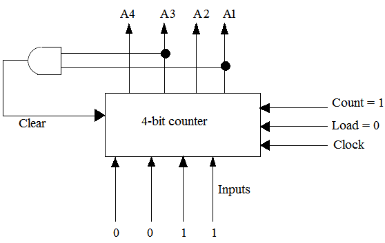
Assume that the counter and gate delays are negligible. If the counter starts at then it cycles through the following sequence:
View worked solution
Answer: C
Based on the standard circuit diagram for this question:
- An AND gate is connected to the Clear input of the counter.
- The inputs to this AND gate are and . Therefore, .
- The Count input is active () and Load is inactive ().
Let's trace the counter states starting from ():
- For states and , the condition and is not met. Thus, , and the counter increments normally on each clock edge:
- On the next clock edge, the counter increments from () to ().
- At state , we have and , which makes the AND gate output .
- According to the function table, when , the counter is cleared to asynchronously (independent of the clock).
Since gate and counter delays are negligible, state is highly transient and immediately resets to . Thus, the stable sequence of states is .
Free practice · Your answers on this page are not saved.