



The block diagram of a frequency synthesizer consisting of a Phase Locked Loop (PLL) and a divide-by- counter (comprising outputs) is sketched below. The synthesizer is excited with a kHz signal (Input ). The free-running frequency of the PLL is set to kHz. Assume that the commutator switch makes contacts repeatedly in the order .
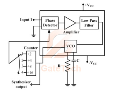
The corresponding frequencies synthesized are:
View answer
Answer: A
Worked explanation not available yet.
Free practice · Your answers on this page are not saved.