Skip to content
Official PYQ · 2020

GATE EC 2020 Set 1 Q10 — Combinatorial Circuits

Explain with AI

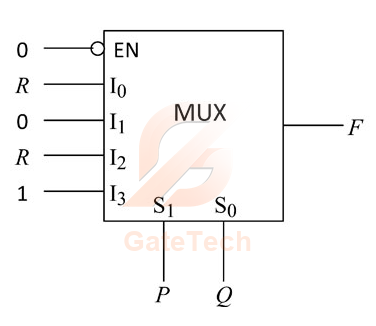
The figure below shows a multiplexer where S1S_{1} and S0S_{0} are the select lines, I0I_{0} to I3I_{3} are the input data lines, EN\text{EN} is the enable line, and F(P, Q, R)\text{F(P, Q, R)} is the output. F\text{F} is 


Choose one option
View answer

Answer: A

Worked explanation not available yet.

Free practice · Your answers on this page are not saved.

Published
Report a correction
Keep exploringMore Combinatorial Circuits questions