



For the circuit shown in the figure, P and Q are the inputs and Y is the output.
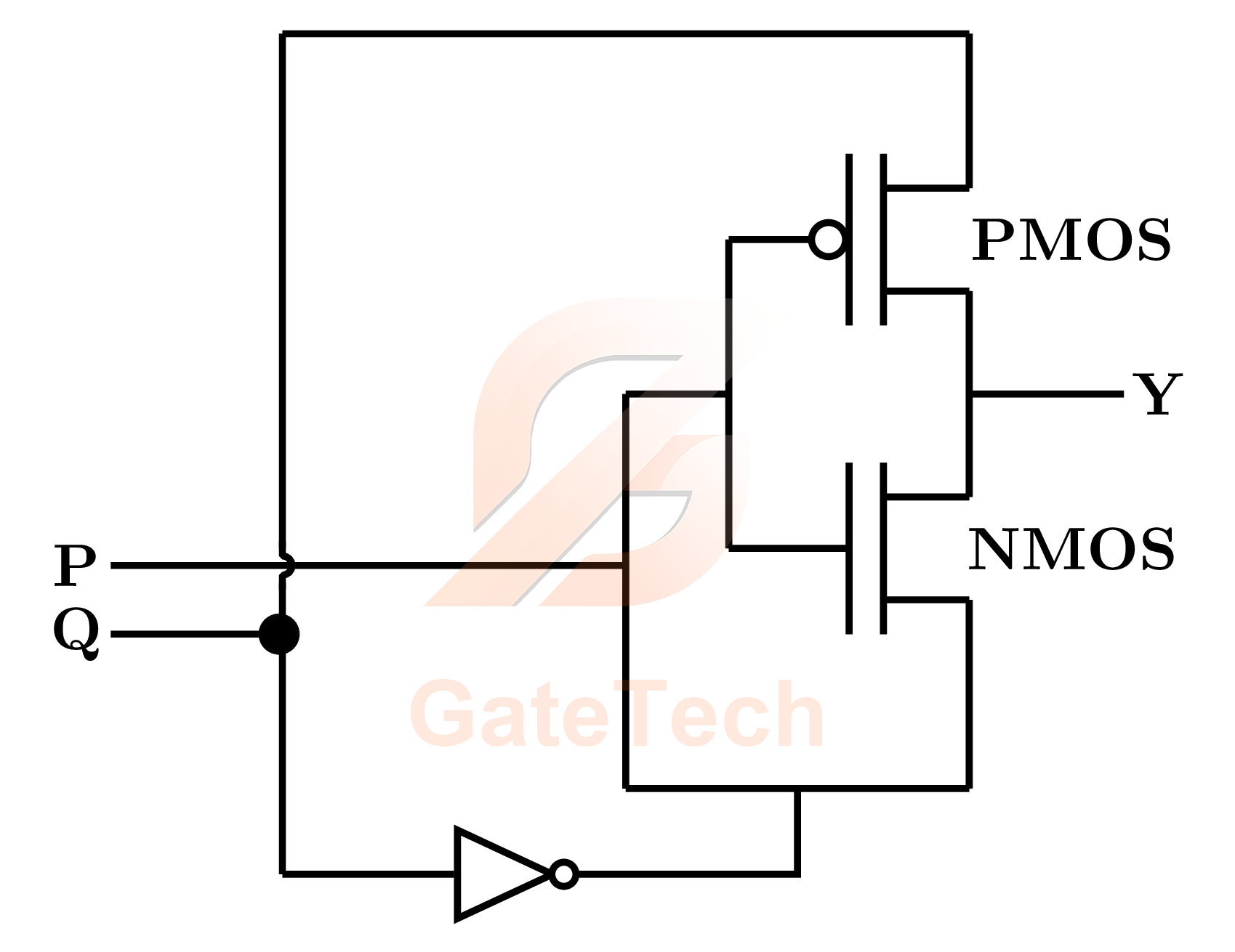
The logic implemented by the circuit is
Marks were awarded to all candidates for this question. It is not scored as a normal quiz.
View answer
Marks to all
Worked explanation not available yet.
Free practice · Your answers on this page are not saved.